- Safety Loop must have only safety equipment
Operating mode: S-Sensor > S-Input module > S-CPU & Co-processor > S-Output module > S-Actuator
System reaction time (process safety time > System reaction time):
 |
| Image from Modicon M580 Safety Manual |
Note: Tcomm_in and out are considered only in the case of RIOs, not when the S-IO card is in the same rack as the PLC. In case of CIP Safety communication, Tcomm_in and out will take in consideration the additional communication time depending on the role of the PLC, i.e. consumer and/or producer. In case of consumer: Network Time Expectation = 4.5x Safe Task Period + 60ms In case of producer: Network Time Expectation = 6x Safe Task Period + 60ms
- Safe state of IO modules: de-energized state (IO Channel, Module or entire system). In Control Expert, it is possible to edit the Fallback state.
- PLC safety code execution: only PERIODIC mode (range between 10...255ms for SAFE task and between 1...255ms for FAST task), not CYCLIC. Default Watchdog is 250ms.
- Safety Hardware: CPU and co-processor (SIL3, PLe), Safety IO (SIL3, PLd 1 channel, PLe 2 channels), Safety Power Supply (SIL3)
- Type 1 and Type 2 non-interfering modules for SIL3: Type 1 examples: backplane (BME XBP 1200), communication card (BME NOC 0301), IO cards, etc
- Commissioning: - Verify Fallback of safety timeout (S_TO), for the safety output modules, is at least greater than (40ms OR 2.5xTsafe), so S_TO min. is 40ms - Set the safety modules in "Lock" mode in the software - "Rebuild All Project" after doing the safety programming - System bits: PLC Firmware: %SW14, Coprocessor FW: %S142, Verification no overrun condition: %S19, max and current SAFE execution time: %SW42 and 43, PLC load: %SW116
- Versions of PLC and RIO: if M580 has FW >v3.20 then RIO must be >v2.60
- S-DI card: BMX SDI 1602 - Power Supply: Internal (supplied by the card via pins 17 (channels 0...3 - ranks A and B) and 18 (channels 4...7 - ranks A and B)) or External - External can detect a cut wire and short-circuit to ground - Internal can detect a cut wire, short-circuit to ground and to 24VDC, cross-circuit - 16 inputs, from pins 1 to 16, organized by: pins 1 and 2 = Input 0 (rank B and A) ... pins 15 and 16 = Input 7 (rank B and A) - mapping inputs to pin and Control Expert
 |
| Image from Modicon M580 Safety Manual |
- Certified Safety Functions and Function Blocks: Prefix "S_"
 |
| Image from Modicon M580 Safety Manual |
- Data separation: Global variables can have data transmitted between the process (non-safety) program and the safety program.
 |
| Image from Modicon M580 Safety Manual |
- Example on how to create a data exchange between PROCESS <-> GLOBAL <-> SAFE
1. Create a GLOBAL variable at the Folder "Variables & FB instances" located in the GLOBAL scope:
2. Create the Input/Output Interfaces in the Program-SAFE > "Variables & FB instances" > "Program Interface". Note that a link with the GLOBAL variable is created in the column "Effective Parameter":
3. Repeat Step-2 in the Process Scope:
4. Example: SCADA routine in Process Scope, sending and receiving data to the Safe Scope via the GLOBAL variables:
NOTE: If a change in these three interfaces must be done (Global, Process and Safety) a compilation error saying that the Global "Variable already exists" may occur. To overcome this error, delete the variables in the Global interface and create again.
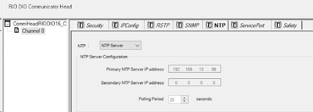
- Configure NTP for the Safety CPU, in order to ensure the CPU and the RIOs are in sync. Go to the hardware configuration, double-clicking on the CPU network card and set the NTP role as NTP Client or Server, with a periodic time update of 20s. Note: The status of the NTP sync between the CPU and the Safety RIOs can be checked by clicking on the module Safe Device DDT > "S_COM_DBG" > "M_NTP_SYNC" and "CPU_NTP_SYNC"
- Safe PLC-to-PLC communication, that are NTP sync'd, can be done via Modbus TCP and two safety FBs: S_WR_ETH_MX and S_RD_ETH_MX.
 |
| Image from Modicon M580 Safety Manual |
- System words for troubleshooting blocking conditions: %SW124, %SW125. Initialization can be done by setting the bit %S0 (or from Control Expert PLC > Init)
- Pg 210
- NTE network time expectation producer - consumer: pg 357


No comments:
Post a Comment