Digital Input sensors are very common in the industry, and they can inform the system about different types of information. Here below some of the most common examples.
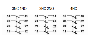
Examples:The Normally Open (NO) auxiliary contact has +24V on the 11 connection and is wired to a Digital Input connection on the terminal 14.
The Normally Open (NO) auxiliary contact has +24V on the terminal 13, and it is wired to a Digital Input connection on the terminal 14.
> Presence Sensor with Emitter and Receiver units: 1-wire connection
Power supply: +24VDC to emitter (L+) and to receiver (L+) 0VDC to emitter (L-) and to receiver (L-) Signal: receiver NO (Out) to DI
> Limit Switch: 2-wire connection
Sensor terminal 11 -> input 9 (L+) // sensor is powered by the DI card Sensor terminal 12 -> input 1 (DI0)
> Push-buttons are typically either 1-wire or 2-wire connection. Normally a 2-wire connection is done and then the +24V is jumped to the other PBs that are in an 1-wire connection.
> Presence Sensor: Magnetic 3-wire PNP (NO) in a 3-wire DI connection
Sensor wire 1 -> input 9 (L+) // sensor is powered by the DI card
Sensor wire 3 -> input 1A (AUX)
Sensor wire 4 -> input 1 (DI0)
This is also the configuration for an inductive sensor with positive switching, where the positive output signal to L-.
Note:
It is good practice to add a fuse when bringing external sensors to the control cabinet. The fuse can protect the system against overcurrent, short-circuit or electrical faults.


No comments:
Post a Comment