In
this post we will see some examples of the MSG (message) instruction from the
Input / Output group, to read and write data on two simulated CPUs on the same
backplane in the RSLogix5000 simulator. The same concept can be applied to CPUs
installed on an industrial network. The MSG can also be used to communicate
data between previous generation CPUs, such as establishing a message exchange
between generation 5000 PLCs with the PLC5 or SLC500.
Create
global objects with the Data Type MESSAGE:

Create
a logic for running the MSG. In this example we created the routine
MSG_Routine, with a timer always active that will execute the message every 5s.

MSG block configuration. In this example the message type is CIP Data Table Read.
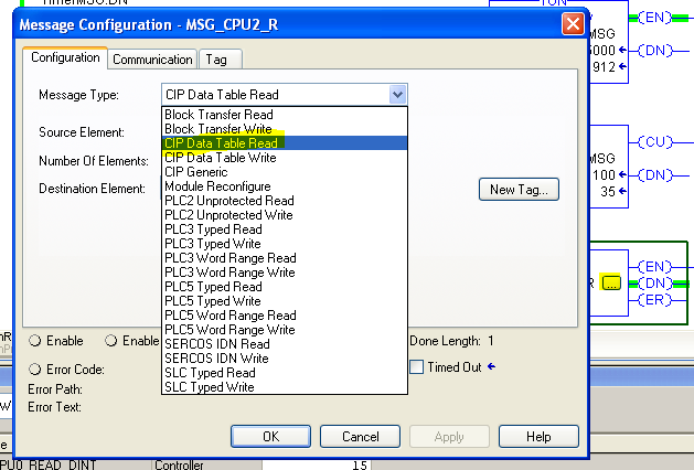
Source, Destination, Size: In the left image it is CPU0 in slot [2] of the
backplane and in the right image it is CPU2 in slot [7]. The name of the source
element, ie source, must correspond with the name of the global Tag created on
the other CPU.

Path selection is done by browsing the desired CPU from the backplane.

The address could also be selected by typing 1, which
indicates communication via the backplane, and the slot number, for example:
" 1, 7 ". If the connection was via an Ethernet-IP network, the path
could be written as 2 and the number of the IP address "2,
192.168.1.19".

Examples: Reading a DINT variable

Reading an Array of DINT. It is important to configure the number of elements so that the size of the array is equal to or less, otherwise an error will occur.


Notes:
Example: MSG READ and WRITE configured in PLC 1.
- Configuration READ on CPU 1:
Message type: CIP Data Table Read
Source: Data_To_CPU1 (this variable is in CPU 2)
Number of elements: 5 (e.g., INT[5] this is the size of the variable being read from CPU 2)
Destination: Data_From_CPU2[0] (this variable is in CPU1)
- Communication:
Path: CPU2_Controller (browse the path and find it in the A1, Ethernet tree)
Method: CIP (with Connected and Cache Connections ticked)
- Configuration WRITE on CPU 1:
Message type: CIP Data Table Write
Source: Data_To_CPU2[0] (this variable is in CPU 1)
Number of elements: 5 (e.g., INT[5] this is the size of the variable being read from CPU 2)
Destination: Data_From_CPU1 (this variable is in CPU2)
- Communication:
Path: CPU2_Controller (browse the path and find it in the A1, Ethernet tree)
Method: CIP (with Connected and Cache Connections ticked)
No comments:
Post a Comment